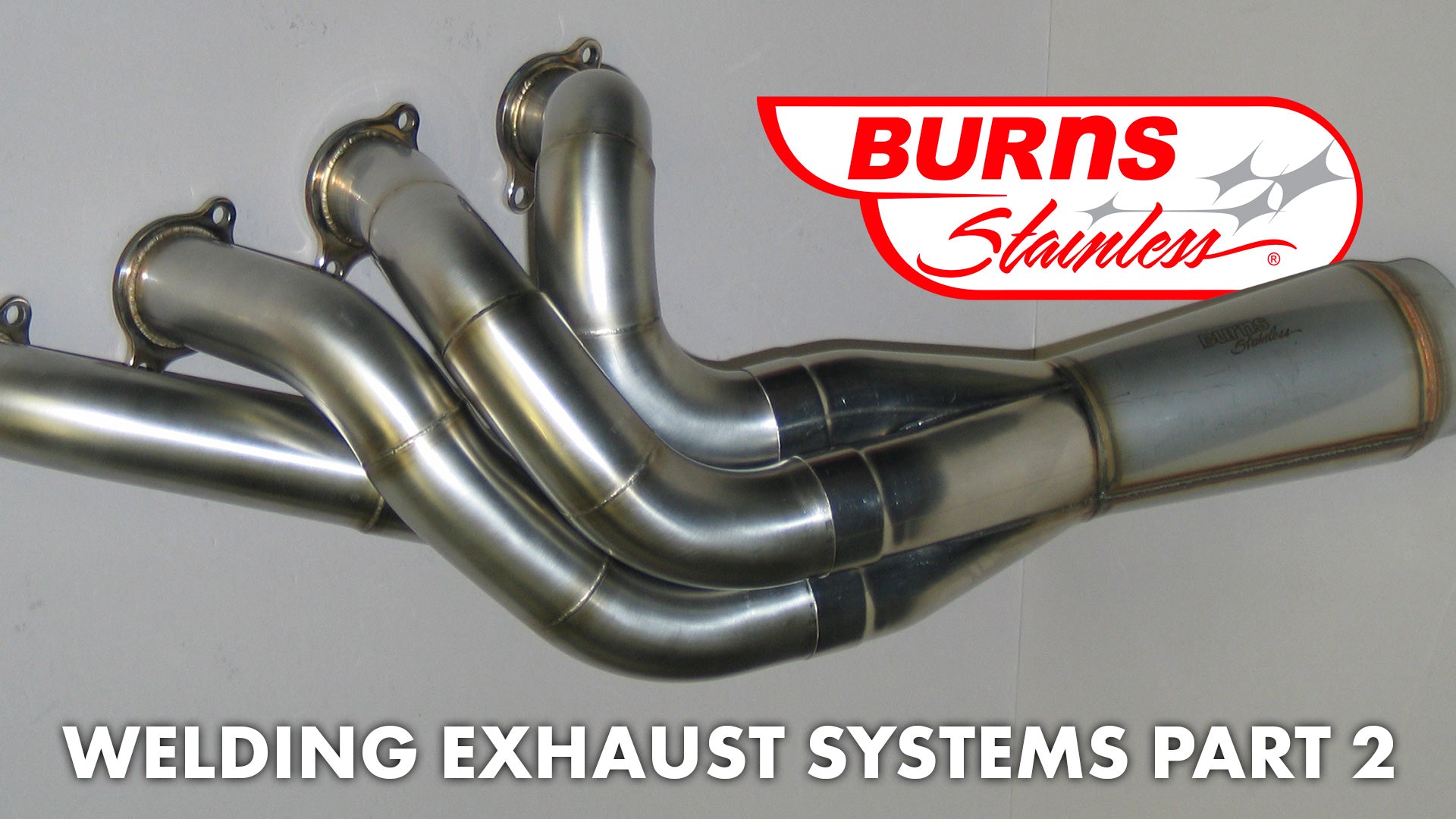
As mentioned in Part 1 of this series, TIG should be employed when welding thin sections of exhaust tubing, especially when using specialized alloys such as stainless steel or Inconel. The header in Figure 1 is an Inconel Pro-Stock header fabricated by Jack Burns from 0.028" wall tubing.
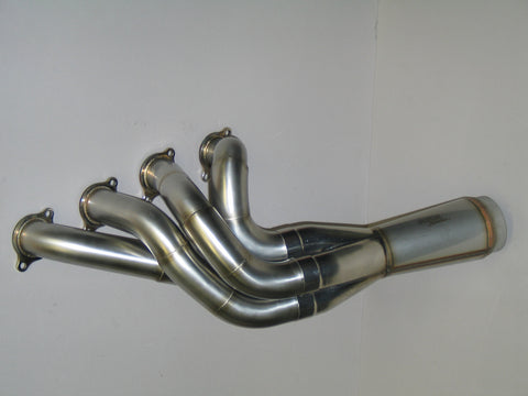
The considerable control of the welding process by the operator and the inert shielding gas help assure proper weld strength for these alloys that have a propensity to form unwanted oxides during heating. This allows for proper welding of thin walled tubing commonly used in Motorsports exhaust applications. Part 2 of the series will focus on the proper preparation of the tube sections for welding.

When welding thin sections of stainless steel tubing as used in racing exhaust headers, care must be taken to properly prepare the joints (Figure 2 – Photo provided by CPR Fabrication). This is a crucial step, and trying to rush through is simply not acceptable. First of all, the tubing must be clean and free of any oily residue. When tubing is mandrel bent, thick lube oils are used to help slide the mandrels through the tubes. Over the past few years, environmental rules have minimized the use of strong organic solvents, so sometimes the tubes will contain residual amounts of lube in the bend area. The residue must be removed from the tube prior to welding. Any residual lube will contaminate your welds. A squirt bottle of acetone and rag usually does the trick.
The next step is to properly fit the tubes. When two sections of tubing are joined, there should be no gaps – and I mean none (Figure 3 - CPR Fabrication). Welders who are used to working with mild steel know how easy it is to fill gaps with the torch and filler rod. This is not acceptable when welding stainless steel as residual stresses can be imparted into the weld. Also, the resultant larger heat affected zone (HAZ) can cause the formation of the aforementioned oxides. Both of which can lead to premature failure. You will also find that excessive gaps will cause your assembly to distort during welding. So after welding, when you fit that header tube that you spent hours fitting together, you'll find that it now hits up against the shock tower and know you should have spent a little more time on fitting. When fitting tubes, you should be able to hold them up to a light and not see any light shining through. Another good test is to hold the tubes together by hand and try "rocking" the tubes together. You should feel no movement.

After properly fitting the tubes, it is time to tack the parts together (Figure 4 - CPR Fabrication). This will be an excellent test of the joint preparation, as any gaps will be "found-out" when you get a "blow-through" when striking the arc. And believe me, blowing through 0.028" wall tubing is not hard to do. Good witness lines are a must when fitting tubes. A fine tipped "Sharpie" is great for this purpose. It should also be noted that there is a good tool on the market to help with the fitment process. It is a tack-welding clamp from IC engine works. The clamp is designed to hold the tubes together before tacking. It is an excellent tool for the novice header builder, though experienced "fabbies" may find them cumbersome. Two tacks per tubing joint are sufficient. You will find that you will need to break tacks from time to time as your header design evolves, so as few tacks as needed is best.

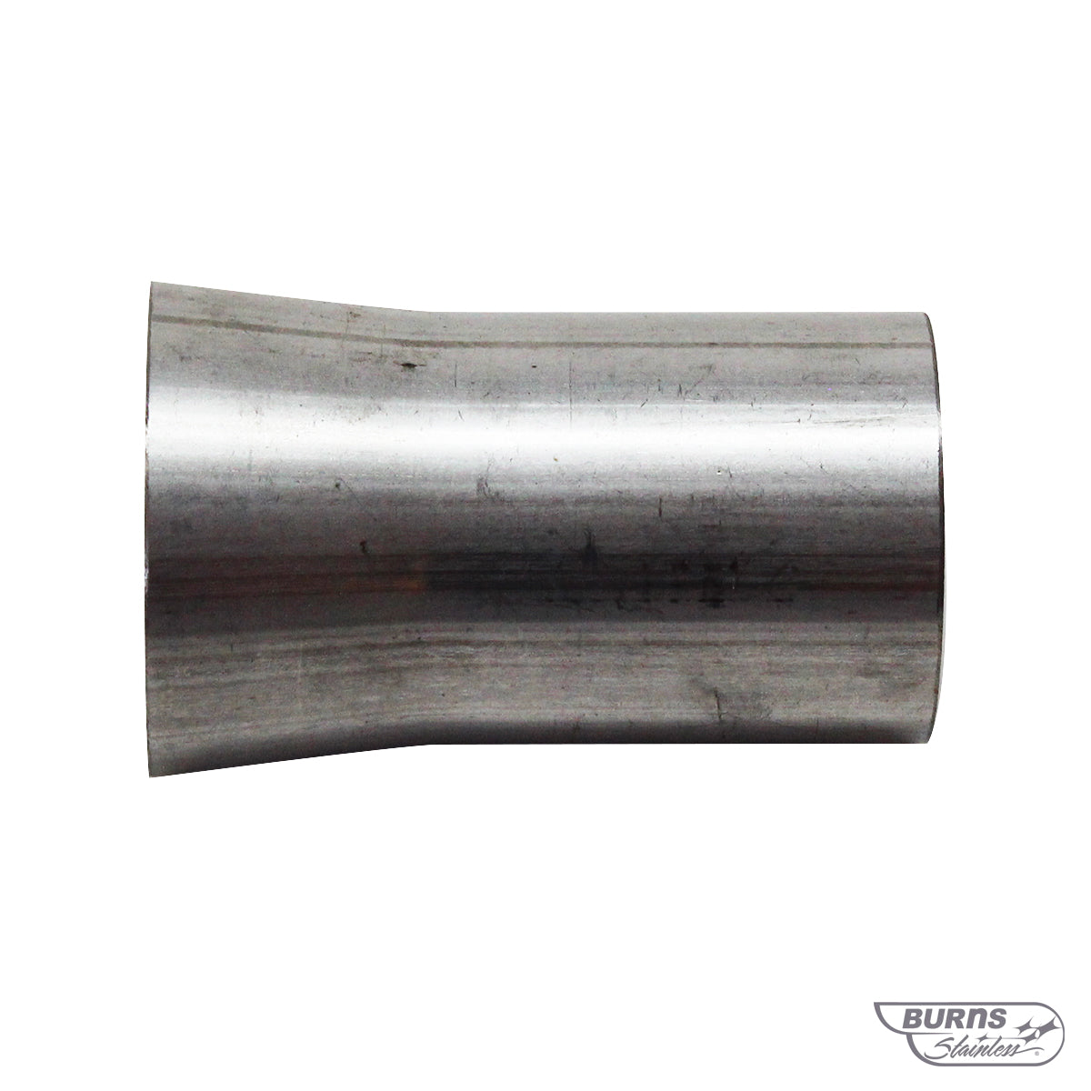
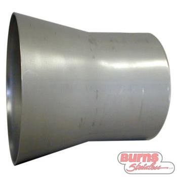
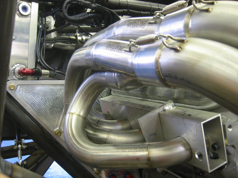
Though not directly related to welding, this is a good time to discuss "cheating bends." We consider a properly cut tubing bend as one where the tube is cut perpendicular to the tangent of the bend (Figure 5). It will often be tempting while fabricating a primary tube to "cheat" the bend, that is, cutting it "off-tangent." This is one of the most common "power-robbers" that is over looked by mediocre fabricators. A few years ago, a professional level drag race customer of ours sent us a tri-Y header to evaluate. The customer had a great header designed by us using our X-design software and fabricated by a customer of ours, Elston Exhaust. The drag race customer was in a hurry to have a new header built for another car, so he sent the header to a local fabricator to have a copy made (Figure 6). While dyno testing the new header, the racer was shocked to see that the duplicated header was down 15 hp! At first glance, the header looked very nice. The welding was nice and it looked to be very close to the copied design. However, upon closer inspection, we noted a few cheated bends as well as some design problems with the collectors. I am sure that the builder did not believe that it would make a difference, but as the saying goes, "the devil is in the details."
Next month we will discuss how to assure strong welds through back-purging
In the Welding Exhaust Systems series: